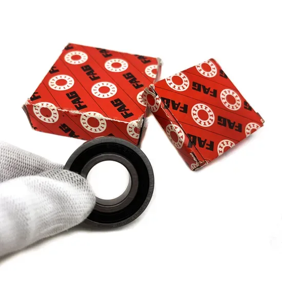

Matching basic outer and inner diameters is not enough for a successful inch-to-metric bearing conversion.
Accurate FAG inch-to-metric cross-referencing requires verifying internal clearance and ABEC tolerances, not just matching basic dimensions, to prevent hidden tolerance traps that cause vibration and line shutdowns.
I still remember the angry call from an Ohio maintenance manager after the Chicago show. He swapped an inch-series FAG bearing with a metric cross-reference I suggested back when I was on the buying side. The inner ring tolerance was off by a few microns, causing severe vibration and a full line shutdown. That failure taught me why inch-to-metric conversions can’t just rely on basic dimension tables. Now on the supplier side, I always check internal clearance and ABEC ratings before confirming any cross-reference. Buyers constantly complain about hidden tolerance traps, so I always lay out the exact dimensional deviations upfront. This approach is critical when using a FAG Inch-to-Metric Shaft Reference to ensure operational stability.
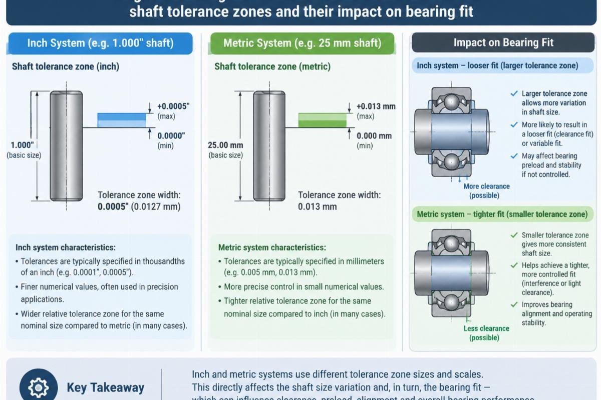
The transition from imperial to metric systems in heavy industry is rarely a simple mathematical conversion. It involves a complex interplay of thermal expansion, load distribution, and manufacturing standards. When engineers or MRO managers attempt to replace an inch-series bearing with a metric equivalent, they often overlook the subtle but critical differences in how these standards define fit and clearance. This guide details the methodology for accurate cross-referencing, ensuring that every replacement maintains the integrity of the original design.
Why Basic Dimension Tables Fail in Inch-to-Metric Conversions?
Basic dimension tables only provide nominal sizes, ignoring the critical tolerance bands that define actual performance.
Most technical catalogs list the bore, outside diameter, and width for both inch and metric bearings. However, these nominal values do not account for the allowable deviation in manufacturing. An inch-series bearing might have a bore tolerance that allows for a slightly looser fit on a shaft compared to its metric counterpart, or vice versa. When these differences are ignored, the resulting interference fit can be too tight, leading to premature heating and seizure, or too loose, causing fretting corrosion and vibration.
Consider the case of an OEM gearbox retrofit where an engineering team replaced inch-series bearings with metric equivalents based solely on nominal dimensions. The inner ring tolerance deviation, measured in microns, created an uneven load distribution across the rolling elements. This mismatch led to severe vibration within hours of operation. The root cause was not the size of the bearing, but the tolerance trap inherent in the conversion process. Using a reliable FAG Inch-to-Metric Shaft Reference helps identify these deviations before installation.
| Conversion Factor | Basic Dimension Approach | Tolerance-Aware Approach |
|---|---|---|
| Bore Size | Matches nominal value | Verifies actual deviation range |
| Fit Type | Assumes standard fit | Calculates required interference/clearance |
| Risk Level | High potential for vibration | Minimized risk of failure |
| Data Source | General catalog | Detailed tolerance charts |
This table highlights the disparity between a superficial check and a thorough technical evaluation. The basic approach is vulnerable to hidden failures, while the tolerance-aware approach is robust against dimensional mismatches. When sourcing replacements, it is essential to look beyond the part number and examine the underlying specifications. A FAG Inch-to-Metric Shaft Reference provides the necessary depth to make these distinctions clear.
Step 1: How to Extract Exact Inch-Series Deviations and ABEC Ratings?
Always check original internal clearance and precision grades before swapping any bearing.
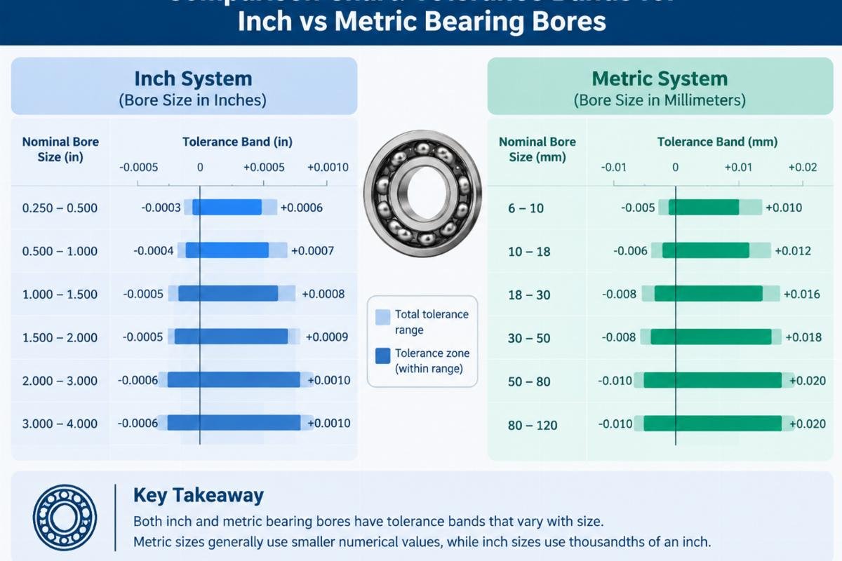
The first step in any cross-reference process is to gather complete data from the existing component. This includes not just the part number, but the specific ABEC rating and internal clearance class. Many inch-series bearings operate with specific precision grades that do not have direct one-to-one equivalents in the metric system without adjustment.
In a recent project involving a heavy fleet hub conversion, we verified dimensional deviations upfront to ensure batch-to-batch consistency. The original inch-series bearings had a specific ABEC rating that dictated their runout and noise levels. By extracting this data, we were able to select metric equivalents that matched not just the size, but the performance characteristics. This level of detail is often missing from generic cross-reference tools, making a specialized FAG Inch-to-Metric Shaft Reference invaluable for engineers.
- Identify the original part number and series.
- Locate the ABEC rating or ISO precision class.
- Determine the internal clearance code (e.g., C3, C4).
- Measure actual shaft and housing dimensions if possible.
Skipping any of these steps can lead to significant operational issues. For instance, assuming a standard clearance when the original required a C3 clearance for thermal expansion can result in binding during operation. The precision grade also affects the lifespan of the bearing under high-speed conditions. By focusing on these parameters, you ensure that the replacement bearing meets the original design intent. This meticulous approach is a hallmark of effective use of a FAG Inch-to-Metric Shaft Reference.

Step 2: How to Calculate Metric Internal Clearance for Your Application?
Match metric C3/C4 clearances to actual operating temperatures to avoid thermal expansion issues.
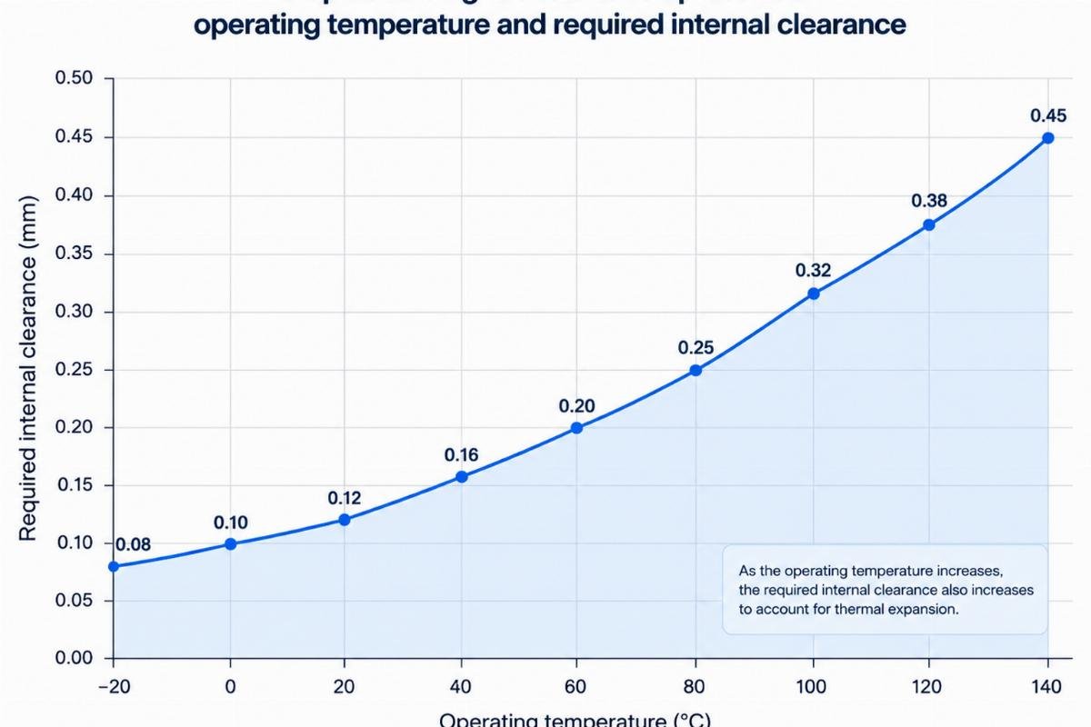
Internal clearance is the space between the rolling elements and the raceways. In inch-to-metric conversions, this parameter is often the most misunderstood. Different applications require different clearances to accommodate thermal growth and load deformation. A bearing that fits perfectly at room temperature may seize up when it reaches operating temperature if the clearance is insufficient.
An MRO conveyor repair scenario illustrates this point well. The maintenance team matched the ABEC ratings but failed to adjust for the internal clearance. The metric equivalent had a standard clearance, while the original inch-series bearing had a C3 clearance. As the conveyor operated, the heat generated caused the inner ring to expand more than the outer ring, reducing the clearance to zero and causing catastrophic failure. By using a FAG Inch-to-Metric Shaft Reference, engineers can calculate the required metric internal clearance based on the operating environment.
- Assess the operating temperature range.
- Determine the thermal expansion of the shaft and housing materials.
- Select the appropriate metric clearance class (C2, C3, C4, etc.).
- Verify the selection against load conditions.
This process ensures that the bearing maintains optimal performance throughout its service life. It is not enough to simply match the part number; the functional requirements of the application must be met. For high-temperature environments, a larger clearance is often necessary. Conversely, for precision applications with minimal thermal variation, a tighter clearance may be preferred. Understanding these nuances is key to successful cross-referencing.
Step 3: How to Verify Metric Shaft and Housing Tolerances?
Align metric tolerance classes with original inch specs to prevent vibration and ensure fit.
The final step in the conversion process is to verify that the metric bearing will fit correctly on the existing shaft and in the housing. Inch and metric systems use different tolerance classes for shafts and housings. A direct substitution without checking these tolerances can lead to improper fit, which is a primary cause of premature bearing failure.
In our supply operations, we often assist buyers in avoiding these tolerance traps through cross-brand equivalent model consultation and technical selection support. For example, a European wind farm operator needed to replace inch-series bearings in a gearbox. By verifying the metric shaft and housing tolerances against the original inch specs, we ensured that the new bearings would fit correctly without modification. This attention to detail prevents vibration and extends the life of the equipment. A comprehensive FAG Inch-to-Metric Shaft Reference includes these tolerance comparisons.
- Check the shaft tolerance class (e.g., k5, m6).
- Check the housing tolerance class (e.g., H7, J7).
- Compare these with the metric bearing’s recommended fits.
- Adjust if necessary to maintain the original fit type.
This verification process is crucial for maintaining the integrity of the machinery. It ensures that the bearing is neither too loose nor too tight, allowing it to perform as designed. By aligning the metric tolerances with the original inch specifications, you eliminate the risk of fit-related failures. This step is often overlooked in quick conversions, but it is essential for long-term reliability. Our technical support team helps clients navigate these complexities, ensuring that every replacement is a perfect fit.

Conclusion
Precision in cross-referencing prevents costly downtime and ensures operational continuity.
Successful inch-to-metric bearing conversion demands a rigorous approach that goes beyond nominal dimensions. By verifying internal clearance, ABEC ratings, and shaft tolerances, engineers can avoid the hidden traps that lead to failure. This methodical process, supported by detailed technical data, ensures that every replacement meets the original design requirements. Utilizing a reliable FAG Inch-to-Metric Shaft Reference is the cornerstone of this strategy, providing the clarity needed for confident decision-making in complex industrial environments.