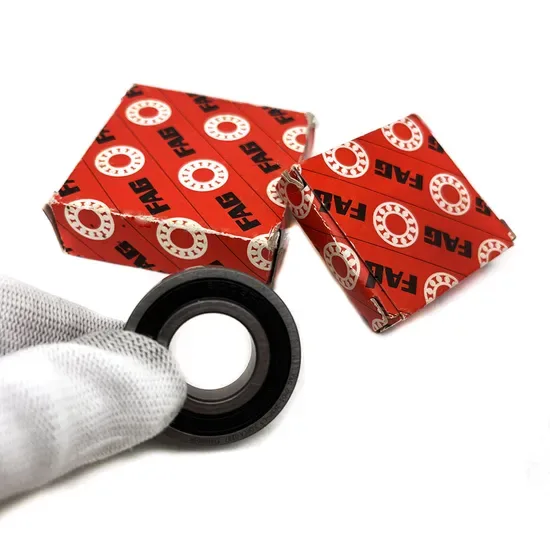

Multiplying by 25.4 is not enough for FAG bearings.
Accurate inch-to-metric conversions on FAG data sheets require verifying nominal historical sizes against current ISO standards, not simple mathematical calculation, to prevent fit failures in mixed-system machinery.
I still remember the dust and heat of a rig site near Riyadh. The crew was trying to install a replacement bearing into a crusher housing that had been sourced from a European OEM. The part number matched the paperwork. The outer diameter looked right. But it would not seat. We measured the shaft and the bore repeatedly. The discrepancy was tiny, barely perceptible to the naked eye, but enough to cause a complete assembly failure. The supplier had provided a conversion chart that used standard decimal rounding. They had ignored the specific nominal dimensions defined in older imperial standards that FAG still references for certain legacy series. That delay cost days of downtime and required emergency air freight for the correct parts. It was a lesson learned in the most expensive way possible: inch conversions on FAG data sheets are not just math; they are a matter of historical engineering context.

This experience is common in regions where industrial infrastructure has evolved through multiple phases of modernization. Many facilities operate with a mix of legacy American-designed equipment and newer European or Asian components. When sourcing replacements, relying on generic conversion tools leads to mismatches. Understanding how to read and verify these conversions is critical for any procurement professional dealing with global supply chains.
Why Do Standard Inch-to-Metric Multipliers Fail on FAG Bearings?
Standard multipliers fail because imperial bearing sizes are based on nominal fractions, not exact decimal equivalents.
The core issue lies in the difference between mathematical conversion and engineering nominalization. A one-inch bearing is not always exactly 25.4 millimeters in every context of fit and tolerance. Historical inch standards, such as those from the American Bearing Manufacturers Association (ABMA), defined sizes based on fractional inches like 1/2, 5/8, or 3/4. When these were adapted into metric systems or when manufacturers like FAG produce bearings for global markets, they maintain specific boundary dimensions that align with these historical norms rather than pure metric series.
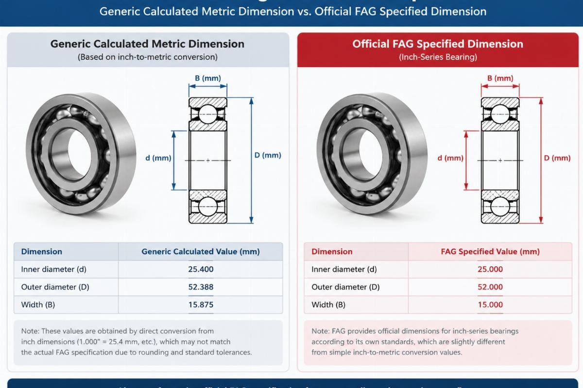
For example, a bearing with a 1-inch bore might have a specified metric equivalent that accounts for standard clearance fits. If you simply multiply 1 by 25.4, you get 25.4 mm. However, the actual manufactured dimension might be designed to interface with a shaft that has a tolerance class allowing for slight variation. Using a generic converter ignores these nuanced tolerances. This is particularly true for tapered roller bearings and spherical roller bearings, where the internal geometry is tightly coupled to the external dimensions.
| Dimension Type | Generic Conversion Approach | FAG Data Sheet Verification Approach | Risk Level |
|---|---|---|---|
| Bore Diameter | Multiply inch value by 25.4 | Check nominal size table for specific series | High |
| Outer Diameter | Round to two decimal places | Verify against ISO 15 boundary dimensions | Medium |
| Width | Use standard decimal equivalent | Confirm with manufacturer tolerance class | Low |
In my work supplying bearings to distributors across the Middle East and Latin America, I often see purchase orders specifying dimensions based on simple calculations. This leads to receiving parts that are technically “correct” by math but functionally wrong for the application. The FAG data sheet provides the authoritative source for these dimensions, listing both the imperial reference and the precise metric manufacturing specification. Ignoring this dual listing is a primary cause of installation errors.
How to Read and Verify Inch Conversions on FAG Data Sheets?
Always locate the specific conversion table within the official technical documentation, not third-party summaries.
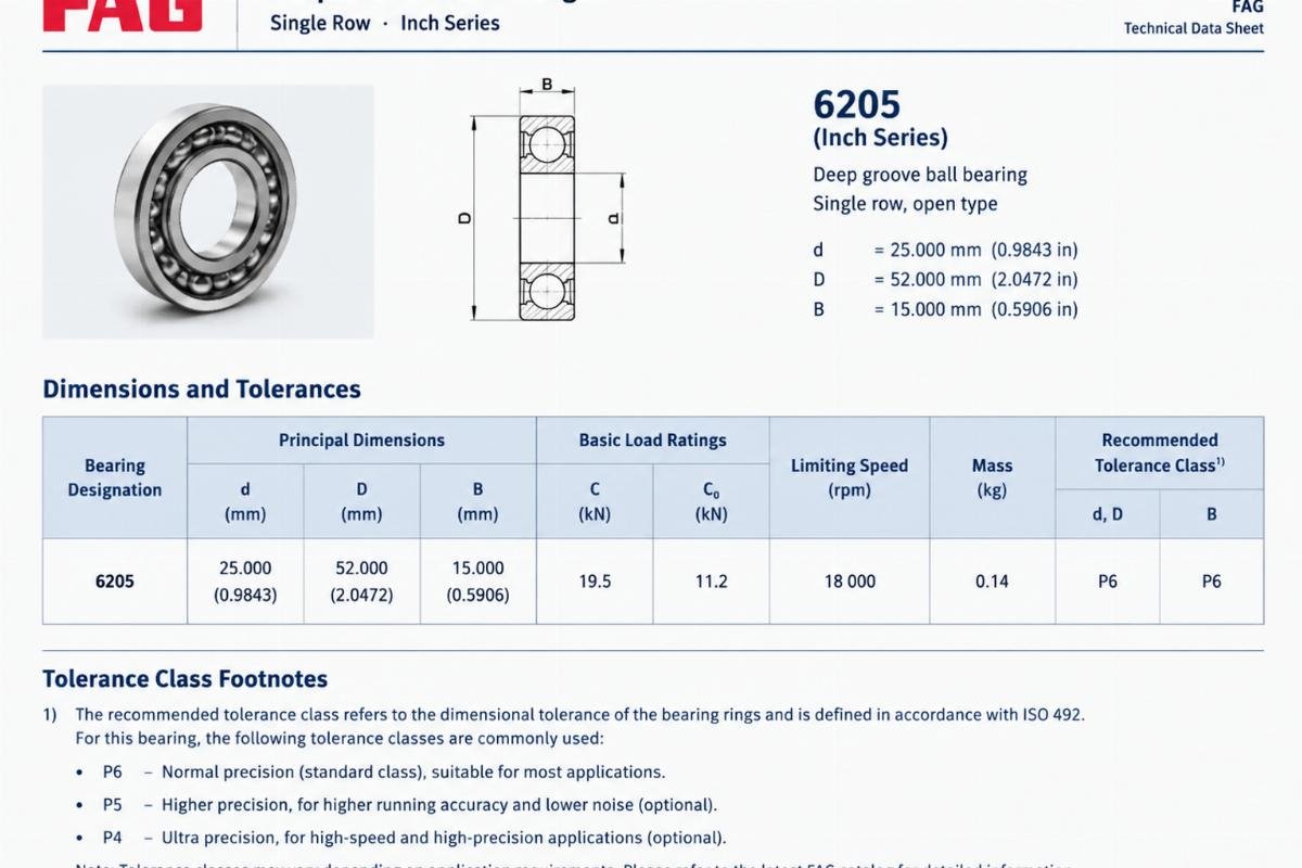
Verifying conversions requires a systematic approach to reading FAG technical documentation. The data sheets are not uniform; they vary by product series and production date. The first step is to identify the specific series code. FAG uses distinct coding for inch-series bearings, often indicated by specific prefixes or suffixes in the part number. Once identified, you must access the current revision of the data sheet. Older revisions may contain outdated conversion factors or refer to superseded standards.
The verification process involves three key checks. First, locate the dimension table. This table will list the bore, outside diameter, and width. Second, check for footnotes regarding tolerance classes. FAG bearings are produced to various precision classes, such as P0 or P6. These classes dictate the allowable deviation from the nominal size. An inch-sized bearing in a higher precision class will have tighter tolerances than a standard metric equivalent. Third, cross-reference the material and heat treatment specifications if available, as these can affect the final dimensional stability after installation.
A common mistake is assuming that all inch conversions are listed in a single master chart. In reality, FAG distributes this information across specific product group documents. For instance, the conversion data for insert bearings differs from that of deep-groove ball bearings. Procurement teams must ensure they are looking at the correct document for the specific bearing type. I recommend maintaining a digital library of the latest data sheets for all active part numbers in your inventory. This allows for quick verification when a question arises during the ordering process.
What Are the Hidden Risks of Rounding Errors in Harsh Environments?
Rounding errors compromise fit integrity, leading to premature failure under thermal stress and heavy loads.
In harsh operating environments, such as mining crushers or oilfield pumps, even minor dimensional discrepancies can have catastrophic effects. Thermal expansion is a significant factor. Metals expand when heated, and the rate of expansion depends on the material and the temperature differential. If a bearing is installed with a fit that is too tight due to a rounding error, thermal expansion can cause the inner ring to seize on the shaft. Conversely, a fit that is too loose can lead to creep, where the bearing rotates on the shaft, causing wear and eventual failure.
I recall a case involving a marine repair project in Southeast Asia. The vessel required an emergency replacement for a main propulsion shaft bearing. The local supplier provided a part that was close enough in size, based on a rounded conversion. However, the operating environment involved constant vibration and temperature fluctuations. Within weeks, the bearing failed due to fretting corrosion caused by micro-movement between the bearing and the housing. The root cause was traced back to a 0.01 mm discrepancy that was deemed negligible during procurement but proved critical in operation.
This risk is amplified in industries where downtime costs are extreme. A failed bearing in a wind turbine or a steel mill roller table can halt production for days. The cost of the bearing itself is insignificant compared to the lost revenue. Therefore, precision in conversion is not just a technical detail; it is a financial imperative. Verifying the exact dimensions on the FAG data sheet ensures that the fit is optimized for the specific operating conditions, reducing the risk of thermal seizure or creep.

How to Ensure Batch Consistency When Sourcing Mixed Imperial/Metric Bearings?
Implement strict traceability and document verification protocols for every mixed-batch order.
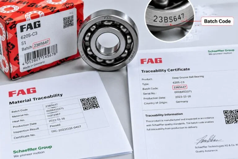
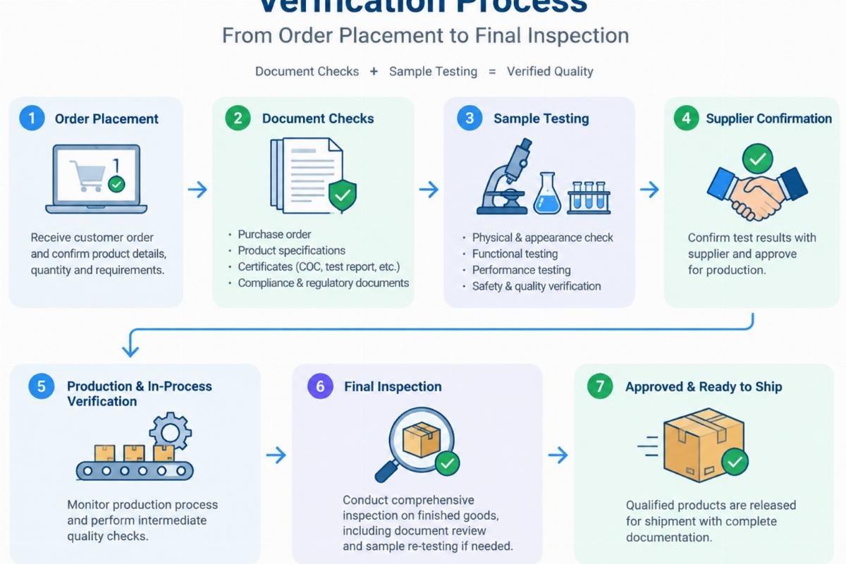
Sourcing bearings from multiple brands and origins introduces variability. Even if two bearings meet the same ISO standard, minor differences in manufacturing processes can lead to fit issues. To ensure consistency, procurement professionals must enforce rigorous documentation checks. Every batch should come with a certificate of conformity that references the specific data sheet version used for manufacturing. This document serves as proof that the dimensions match the expected specifications.
Traceability is another critical element. Knowing the origin of the bearing allows for verification of the manufacturing standards. Reputable suppliers maintain records that link each part number to its production batch and quality control data. This level of transparency is essential when dealing with inch conversions, as it allows for audits if issues arise. I advise buyers to request sample inspections for large orders, especially when introducing a new supplier or a new bearing series. Measuring a sample against the data sheet specifications provides immediate confirmation of accuracy.
Furthermore, technical support plays a vital role in maintaining consistency. Suppliers who offer cross-brand equivalent model consultation can help identify potential mismatches before they become problems. By leveraging their expertise, buyers can navigate the complexities of mixed imperial and metric systems more effectively. This proactive approach minimizes the risk of receiving incompatible parts and ensures smooth installation in the field.
Conclusion
Precision in inch conversions prevents costly operational failures.
Accurate interpretation of FAG data sheets is essential for anyone procuring bearings for mixed-system machinery. By understanding the limitations of simple mathematical conversions and adhering to official documentation, buyers can avoid the pitfalls of mismatched dimensions. This diligence protects against downtime, reduces maintenance costs, and ensures the reliability of critical industrial equipment. Trusting verified data over generic rules is the hallmark of professional procurement.