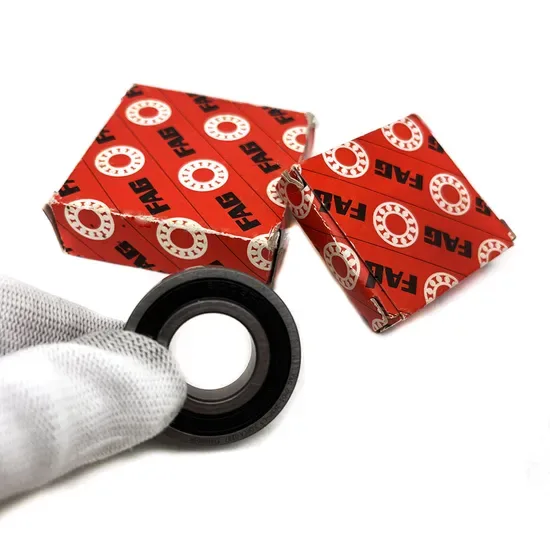

Brute force is the fastest way to destroy a helical gear shaft.
To safely remove FAG bearings from helical gear shafts, you must avoid direct impact on the inner ring. The correct method involves using hydraulic pullers with precise axial alignment or induction heating to expand the inner ring locally, ensuring zero damage to the shaft surface and maintaining the integrity of the interference fit for reinstallation or replacement.
I still remember the smell of burnt oil and metal dust in that workshop in Linyi. A maintenance team had just pulled a cylindrical roller bearing off a critical helical gear shaft using a sledgehammer and a chisel. They thought they were saving time. Instead, they created micro-cracks in the shaft shoulder and scored the inner ring raceway. When the reducer was reassembled, it ran smooth for only a few days before vibrating itself apart. That failure cost them weeks of downtime and a new shaft assembly. Since then, I have watched countless technicians make the same mistake, treating precision components like scrap metal. Proper extraction is not just about removal; it is about preserving the mating surfaces that define the gearbox’s life.
Understanding why this process fails requires looking at the mechanics of the assembly. Helical gears generate both radial and axial loads, which means the bearings are often mounted with tight interference fits to prevent creeping. When you apply uncontrolled force, the stress concentrates on small contact points rather than distributing evenly across the ring. This is where the difference between a successful overhaul and a catastrophic failure lies.
Why Helical Gear Shafts Require Special Extraction Care?
Helical gear shafts are not simple rotating rods. They are complex mechanical interfaces where the bearing inner ring acts as a critical spacer and load transmitter. The geometry of helical gears introduces axial thrust that pushes against the bearing shoulders. To counteract this, manufacturers design the shaft with precise tolerances, often requiring an interference fit that holds the bearing securely under high torque.
When a bearing seizes due to corrosion, fatigue, or lack of lubrication, the bond between the steel inner ring and the shaft becomes incredibly strong. Attempting to break this bond with impact tools transfers shock waves through the bearing steel. Since bearing steel is hardened to resist wear, it is also brittle. A sharp blow can cause the inner ring to fracture or, more commonly, transfer that energy into the softer shaft material, gouging the surface.
I once inspected a returned shaft from a mining crusher application. The customer claimed the bearing had failed prematurely. Upon closer examination with a magnifying lens, I found tiny indentations along the shaft shoulder where a hammer had struck a drift pin. These imperfections acted as stress concentrators. Under the cyclic loading of the helical gear, a fatigue crack initiated from one of these dents, eventually leading to shaft fracture. The bearing itself was fine; the installation method had doomed the assembly.
This is why standard ball-peen hammers have no place in precision maintenance. The goal is to apply a steady, increasing force that overcomes the friction of the interference fit without exceeding the yield strength of the shaft material. For FAG bearings, which are engineered for high precision and load capacity, respecting the material properties is non-negotiable.

What Tools Are Essential for Safe Bearing Removal?
The right tool does not just make the job easier; it makes the job possible without collateral damage. For helical gear shafts, two categories of tools dominate professional maintenance: mechanical pullers and thermal expansion devices.
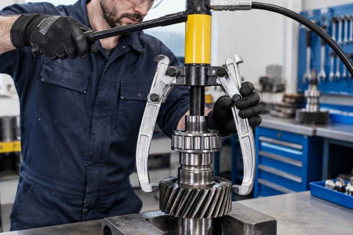
Hydraulic pullers are the gold standard for large cylindrical roller bearings. Unlike mechanical screw pullers, which require significant physical effort and can jerk if the thread binds, hydraulic systems provide smooth, continuous force. The key feature to look for is a self-centering mechanism. If the pulling force is not perfectly axial, the bearing will tilt, binding against the shaft and potentially scoring the bore. A high-quality hydraulic puller allows for tonnage adjustment, ensuring you apply only the necessary force to break the fit.
Induction heaters offer a different approach. Instead of pulling, they expand. By placing an induction coil around the inner ring, you can heat the steel rapidly. Steel expands when heated. If you heat the inner ring while keeping the shaft cool, the diameter of the ring increases, loosening the interference fit. This method is particularly effective for tight fits where pulling force alone might risk bending the shaft. However, temperature control is vital. Overheating can alter the metallurgical structure of the bearing steel, reducing its hardness and load-carrying capacity.
In my experience supplying FAG bearings for helical gear shafts, I often see workshops using open flames from torches. This is a dangerous practice. Open flames create uneven hot spots, leading to warping. Induction heating provides uniform, controlled heat distribution. For distributors and MRO teams, investing in portable induction units pays for itself by preventing the need for shaft replacements.
| Tool Type | Mechanism | Risk Level | Best Application |
|---|---|---|---|
| Hydraulic Puller | Axial tensile force | Low (if aligned) | Large interference fits, accessible shaft ends |
| Induction Heater | Thermal expansion of inner ring | Low (if controlled) | Tight fits, sensitive shaft materials |
| Mechanical Screw Puller | Manual tensile force | Medium | Small bearings, low interference fits |
| Sledgehammer/Drift | Impact shock | High | Never recommended for precision shafts |

How to Execute the Step-by-Step Pulling Process?
Executing a safe removal is a sequence of disciplined actions. There is no shortcut that does not compromise the component. Here is the procedure I recommend for extracting FAG bearings from helical gear shafts.
First, clean the area thoroughly. Remove any grease, dirt, or debris from the shaft end and the bearing face. Contaminants can interfere with the grip of the puller claws or the efficiency of the induction heater. Inspect the shaft end for any burrs that might hinder the puller’s seating.
Second, select the appropriate puller claws. For cylindrical roller bearings, the claws must grip the inner ring firmly. If the inner ring is not accessible, you may need to use a bearing splitter or cut the outer ring carefully to expose the inner race. Never grip the outer ring or the cage, as these components are not designed to withstand pulling forces and will deform instantly.
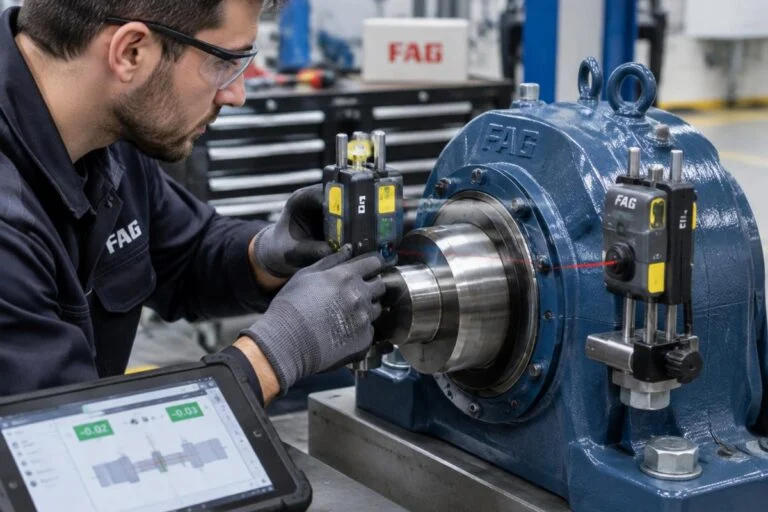
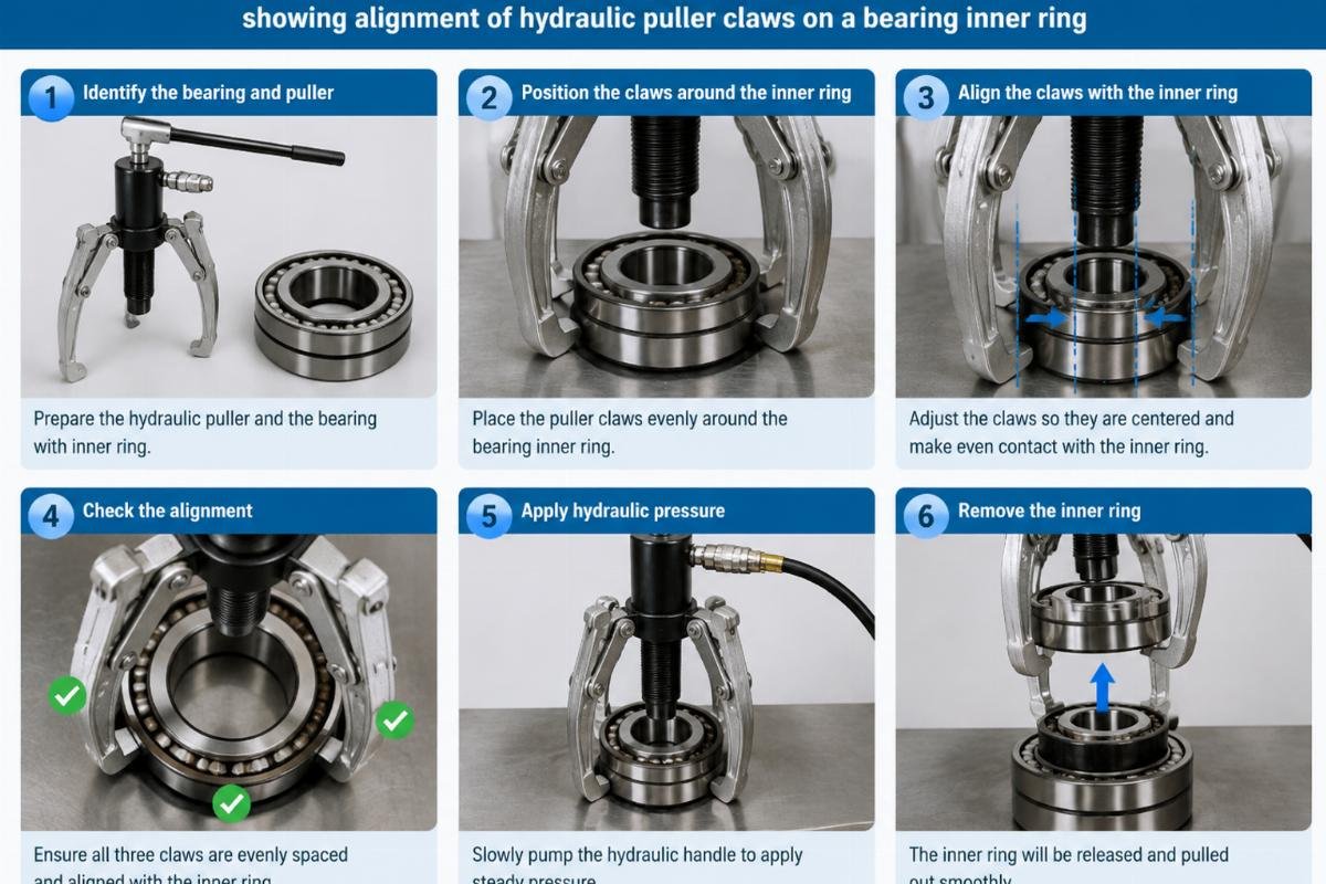
Third, align the puller. Center the forcing screw or hydraulic piston exactly on the shaft centerline. Use a dial indicator if necessary to verify alignment. Misalignment is the primary cause of shaft damage during pulling. Tighten the claws evenly to ensure they share the load equally.
Fourth, apply force gradually. If using a hydraulic puller, pump the handle slowly. Watch for any signs of tilting. If the bearing does not move after reaching a reasonable pressure, stop. Do not increase pressure indefinitely. At this point, apply heat. Use an induction heater to warm the inner ring to the recommended temperature, typically around 80-100 degrees Celsius, depending on the fit.
Fifth, continue pulling while the ring is expanded. The combination of thermal expansion and axial force should release the bearing smoothly. Once free, inspect the shaft immediately. Look for any discoloration or scratches. Clean the shaft surface with a fine emery cloth if minor roughness is present, but do not remove significant material.
A case from a Southeast Asian cement plant illustrates this well. Their team was struggling to remove a stuck bearing on a main reducer. They applied maximum hydraulic pressure, but the bearing would not budge. Instead of forcing it, they paused, applied induction heat for five minutes, and then resumed pulling. The bearing slid off effortlessly. The shaft remained pristine, ready for the new FAG bearing installation.
How to Inspect the Shaft and Bearing Post-Extraction?
Removal is only half the battle. The condition of the shaft determines the success of the next installation. After extracting the bearing, you must perform a thorough inspection.
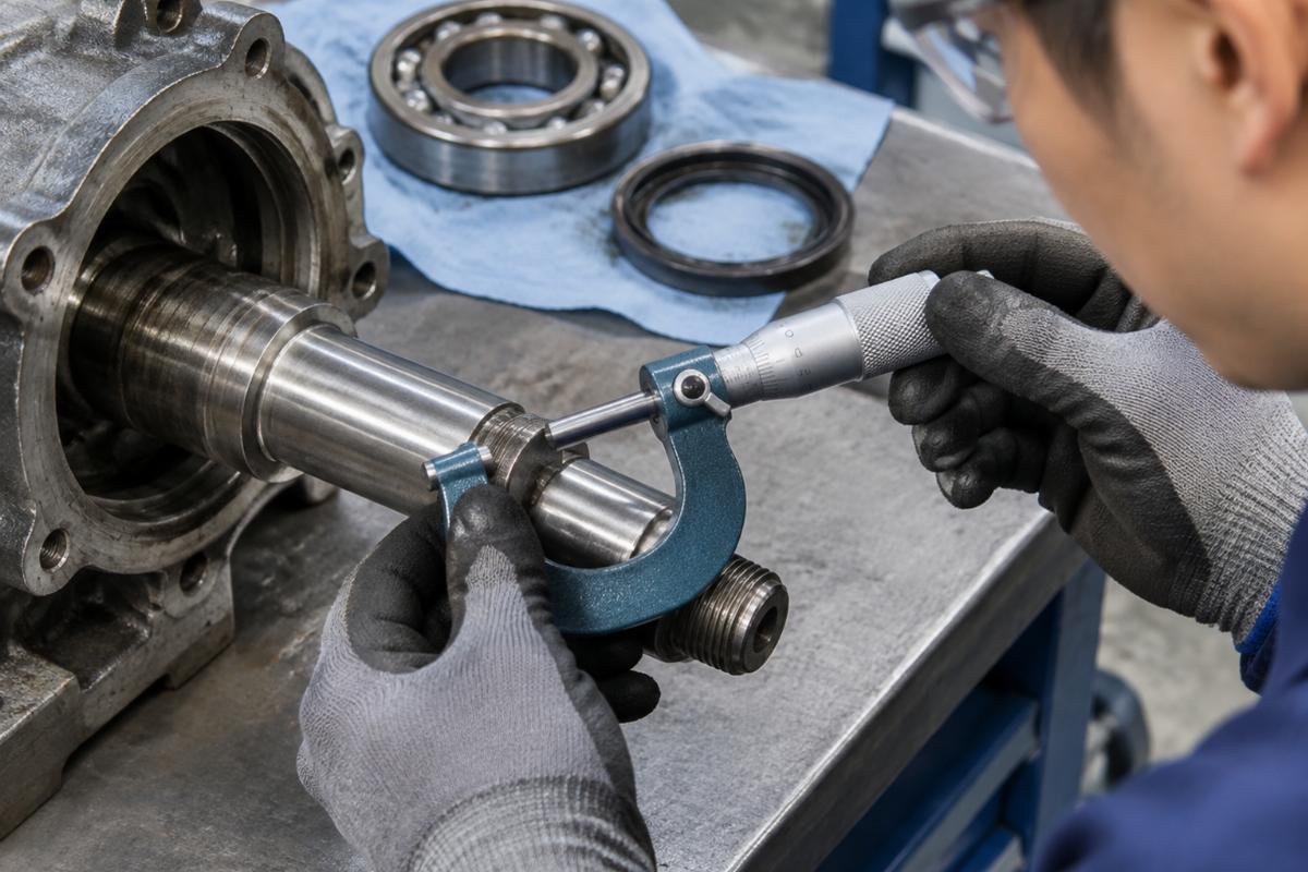
Check the shaft shoulder for squareness and surface finish. Any nicks or burrs must be removed. A rough surface can act as a file against the new bearing’s inner ring, causing premature wear. Use a micrometer to measure the shaft diameter at multiple points. Ensure it has not been stretched or deformed by the pulling process. If the diameter has changed beyond the tolerance limits, the shaft must be repaired or replaced. Installing a new FAG bearing on a damaged shaft is a waste of resources.
Inspect the extracted bearing if it is being analyzed for failure. Look for patterns of damage. Smearing on the inner ring bore indicates slipping, which suggests the original fit was too loose or the lubrication failed. Cracks or spalling point to fatigue or overload. This analysis helps prevent recurrence.
For distributors and end-users, keeping records of these inspections is valuable. It helps in predicting maintenance intervals and selecting the right bearing type for future upgrades. If you notice consistent damage on shafts, it may indicate a systemic issue with the installation process or the operating conditions of the helical gear reducer.
We supply genuine FAG cylindrical roller bearings along with technical datasheets that specify the exact tolerance classes and fit recommendations. Having access to these documents ensures that when you reinstall, you are matching the new bearing to the shaft’s current condition accurately. Precision is not just about the part; it is about the entire system.
Conclusion
Proper extraction preserves the asset.
Removing FAG bearings from helical gear shafts demands patience and the right tools. Avoid impact methods that risk shaft integrity. Use hydraulic pullers and induction heating to ensure a clean, damage-free removal. Inspect the shaft thoroughly before installing the replacement. This disciplined approach minimizes downtime and extends the life of your gear reducers.